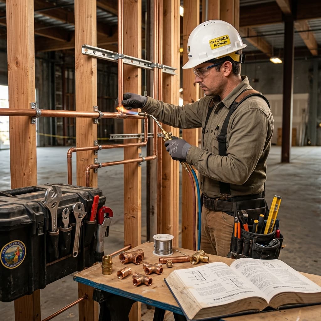

# CPC Section 422: Water Heater Installation and Temperature/Pressure Relief Valve Requirements
Understanding CPC Section 422 and Water Heater Safety
The California Plumbing Code Section 422 establishes comprehensive requirements for pressure vessel water heater installation that every C-36 licensed plumber must master. This critical section addresses one of the most important safety systems in residential and commercial plumbing: the temperature/pressure relief valve and its proper sizing, installation, and maintenance.Water heaters represent some of the most dangerous appliances in any building. Without proper relief valve protection, excessive pressure and temperature buildup can lead to catastrophic explosions, scalding injuries, and property damage. Understanding CPC Section 422 isn't just about passing your exam—it's about protecting lives and property.
The Basics: What Is a Pressure Vessel Water Heater?
Before diving into specific code requirements, let's clarify terminology. A pressure vessel water heater is any storage-type water heater that operates under pressure. This includes:- Standard residential storage tank water heaters
- Commercial water heater tanks
- Indirect water heating systems
- Pressurized hot water storage vessels
CPC Section 422.1: General Requirements
CPC Section 422.1 establishes that all water heaters must be:
- Approved for use and properly labeled
- Installed in accordance with manufacturer's instructions (critical phrase for exam questions)
- Equipped with temperature and pressure relief valves meeting specific standards
- Located and vented appropriately to prevent hazards
Temperature/Pressure Relief Valve Requirements Under CPC 422
CPC Section 422.2: Relief Valve Installation Requirements
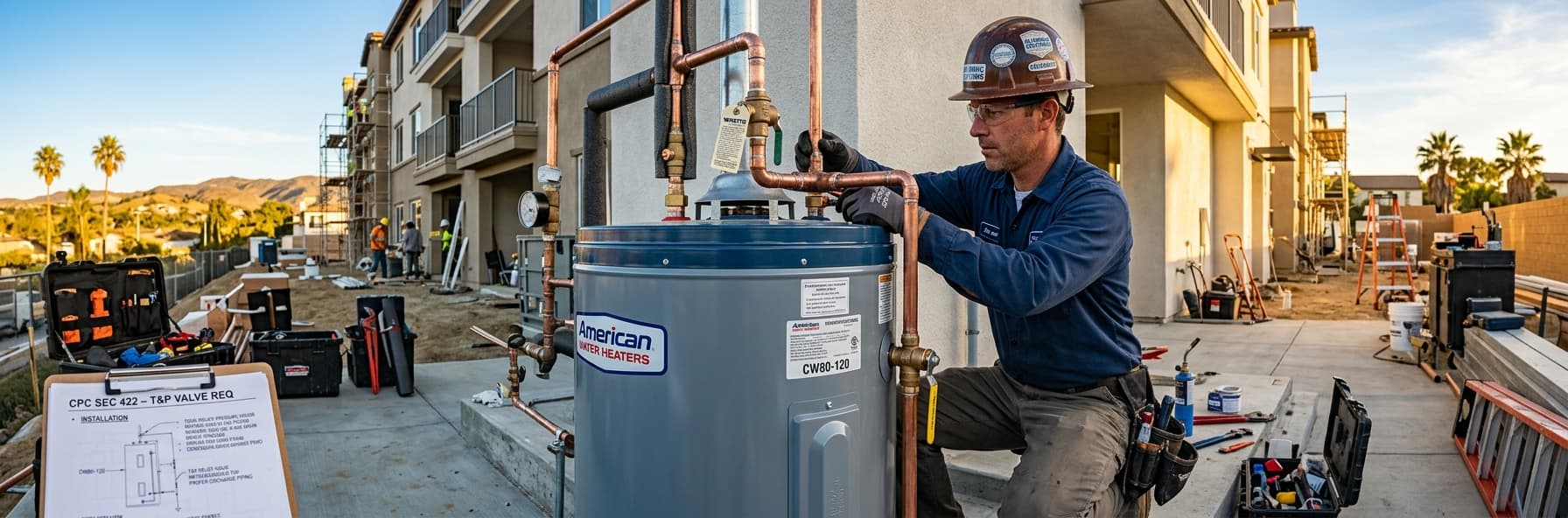
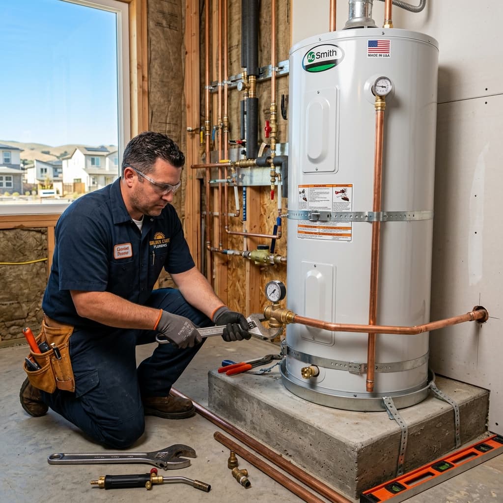
The temperature/pressure relief valve (often called a T&P valve or TPR valve) is the primary safety device protecting against dangerous pressure buildup. CPC Section 422.2 mandates: #### Valve Location and Placement- Relief valves must be installed in the hottest part of the water heater
- For tank water heaters, this is typically in the top 2 inches of the tank
- Valves must be located on the water supply side of any isolation valve
- If an isolation valve is installed between the tank and relief valve, a second relief valve must be installed below the isolation valve (creating a trap that could pressurize)
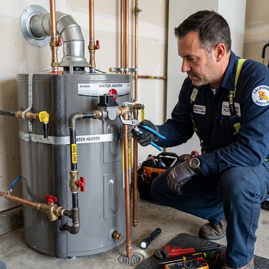
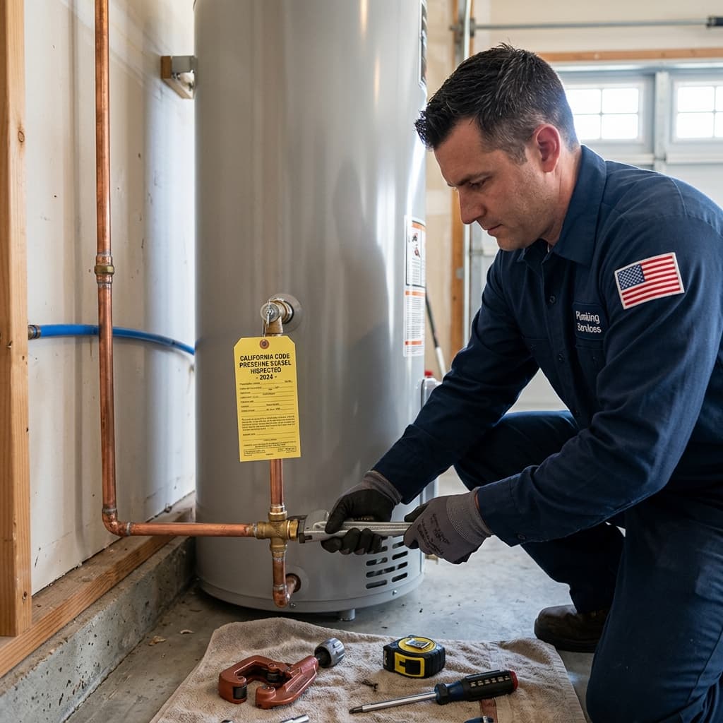
- Relief valves must discharge to the lowest floor level or outdoors
- Discharge must be visible and accessible for inspection
- The discharge line cannot have a trap (air gap preferred)
- Maximum 6-foot discharge line for residential installations (without special approvals)
- Discharge lines must have a minimum 3/4-inch diameter for residential units
- Discharging into a floor drain (trapping potential)
- Discharging into a sewage system without proper venting
- Undersized discharge piping
- Inaccessible discharge (behind walls or fixtures)
CPC Section 422.3: Relief Valve Sizing Requirements
This is where many C-36 candidates struggle. Proper sizing is non-negotiable and is heavily tested.#### The Sizing Formula
The temperature/pressure relief valve capacity must equal or exceed the water heater's BTU input rating. The formula is:Relief Valve Capacity (GPM) ≥ Water Heater Input (BTU/hr) ÷ 12,000
- Water heater input: 40,000 BTU/hr
- Required relief valve capacity: 40,000 ÷ 12,000 = 3.33 GPM
- You would need a minimum 3.5 GPM relief valve (rounded to standard sizes)
#### Why This Matters
The relief valve must be capable of discharging water at the rate it's being heated. If you install an undersized relief valve, pressure will build up faster than the valve can discharge it—defeating its safety purpose entirely. Oversizing is acceptable (more conservative), but undersizing is a code violation and safety hazard.
#### Combination Relief Valves
Many residential installations use combination temperature/pressure relief valves that:- Relieve at a set temperature (typically 210°F)
- Relieve at a set pressure (typically 150 PSI)
- Whichever condition is reached first triggers relief
CPC Section 422.4: Pressure Relief Valve Specifications
Beyond sizing, the relief valve itself must meet specific standards:
- ASME certification (American Society of Mechanical Engineers)
- UL listed (Underwriters Laboratories) or equivalent approval
- Preset to manufacturer's specifications (field adjustment rarely permitted)
- Temperature relief component set to 210°F minimum
- Pressure relief component appropriate to the tank's rated pressure (typically 150 PSI for residential)
Installation Best Practices from CPC Section 422
Material Requirements
The discharge line from a relief valve must be:- Copper tubing (most common)
- Chlorinated polyvinyl chloride (CPVC) tubing
- Stainless steel tubing (for condensing water heaters)
- PEX tubing (in some jurisdictions, with local approval)
- Standard PVC (may be damaged by hot water)
- Galvanized steel (corrosion risk)
- Lead-containing materials
Support and Anchoring
- Discharge piping must be adequately supported per general support requirements
- Piping cannot be concealed in walls (must remain accessible)
- Every change of direction requires proper support
Temperature and Pressure Gauges
While not always required by CPC Section 422 itself, many jurisdictions and manufacturer specifications require:- A thermometer to monitor water temperature
- A pressure gauge to monitor tank pressure
- These help identify relief valve issues before problems develop
Common CPC Section 422 Violations and Exam Scenarios
Violation #1: Undersized Relief Valves
Scenario: A 75-gallon residential water heater with 40,000 BTU/hr input has a 3 GPM relief valve installed. Analysis: 40,000 ÷ 12,000 = 3.33 GPM required. A 3 GPM valve is undersized and violates CPC 422.3. Correct Answer: Install a minimum 3.5 or 4.4 GPM relief valve.Violation #2: Relief Valve Below Isolation Valve
Scenario: An isolation ball valve is installed between the water heater and relief valve with no second relief valve downstream. Analysis: If the isolation valve closes, water in the tank cannot be relieved, creating a dangerous pressure trap. Correct Answer: Either install a second relief valve below the isolation valve, or use a special isolation valve that includes its own internal relief (isolation valve with integrated check and relief).Violation #3: Improper Discharge Routing
Scenario: A relief valve discharge line is routed to a floor drain without an air gap. Analysis: A floor drain trap can create backpressure on the relief valve, preventing proper operation. Discharge must be visible and accessible. Correct Answer: Route discharge to an open, visible location (floor, exterior, or proper indirect waste).Violation #4: Missing Relief Valve
Scenario: A tankless water heater is installed without a relief valve. Analysis: While tankless units have different requirements than storage tanks, they still require relief protection. Refer to manufacturer specifications and applicable code sections. Correct Answer: Tankless systems may use different relief mechanisms—verify manufacturer requirements and local code adoption.Water Heater Sizing and Relief Valve Selection
Determining Input Rating
To properly size a relief valve, you must first identify the water heater's input rating:- For gas water heaters: Listed on the nameplate in BTU/hour
- For electric water heaters: Calculate as (watts × 3.412) or use efficiency rating
- For heat pump systems: Use manufacturer's rated input
Storage Capacity Considerations
While storage capacity (tank volume) doesn't directly affect relief valve sizing, it's important for understanding:
- Expansion volume: Heated water expands; larger tanks may require expansion tanks per CPC Section 422.5
- Recovery rate: Faster recovery (higher input) requires larger relief valves
- System design: Commercial systems with high inputs may require industrial-grade relief valves
Recent Updates and California Code Amendments
California's plumbing code is regularly updated. Current emphasis areas include:
- Water heater efficiency standards (affecting input ratings)
- Tankless water heater integration (different relief requirements)
- Green plumbing practices (expanded expansion tank requirements)
- Solar water heater systems (hybrid configurations)
Practical Application: Step-by-Step Installation
When installing a water heater according to CPC 422:
- Verify specifications - Check manufacturer's input rating and tank pressure rating
- Calculate relief capacity - Input BTU ÷ 12,000 = minimum GPM
- Select valve - Choose ASME/UL-listed valve meeting or exceeding calculated capacity
- Locate valve - Install in hottest part of tank (top 2 inches for storage tanks)
- Install discharge line - Use proper materials, minimum 3/4-inch, no traps
- Route discharge - To lowest floor level or exterior, visible and accessible
- Support piping - Every 4 feet maximum for horizontal runs
- Test operation - Verify valve discharges when lever lifted (manual test)
- Label components - Ensure all parts are clearly marked and identifiable
Exam Strategy and Key Takeaways
For C-36 exam success on water heater relief valve questions:
- Memorize the formula: Relief GPM = Input BTU ÷ 12,000
- Understand isolation valve dangers: Relief valves below isolation valves create dangerous traps
- Know discharge requirements: Visible, accessible, no traps, proper routing
- Remember ASME/UL: Relief valves must be certified and labeled
- Apply manufacturer requirements: Always defer to water heater manufacturer specifications when stricter than code
---
Related Reading: