
# Combination Drain, Waste, and Vent (DWV) System Design: CPC Section 403 Compliance and Sizing
Introduction: Understanding California Plumbing Code DWV Systems
The California Plumbing Code drainage system requirements present one of the most critical components tested on the C-36 Part 2 examination. Combination drain, waste, and vent (DWV) systems represent the integrated approach to managing wastewater and maintaining proper ventilation within residential and commercial buildings. Understanding CPC Section 403 compliance and sizing calculations is essential for plumbers, engineers, and contractors seeking certification.
DWV system design isn't merely about moving water from point A to point B. It's a sophisticated engineering challenge requiring knowledge of fluid dynamics, pressure differentials, trap seal integrity, and code compliance. This comprehensive guide explores the foundational requirements, sizing methodologies, and practical applications you'll encounter on your C-36 exam.
What Is a Combination DWV System?
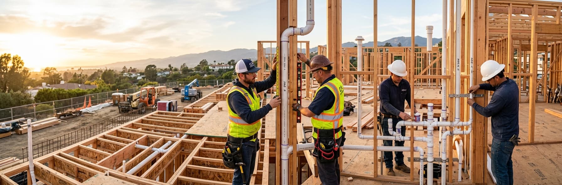
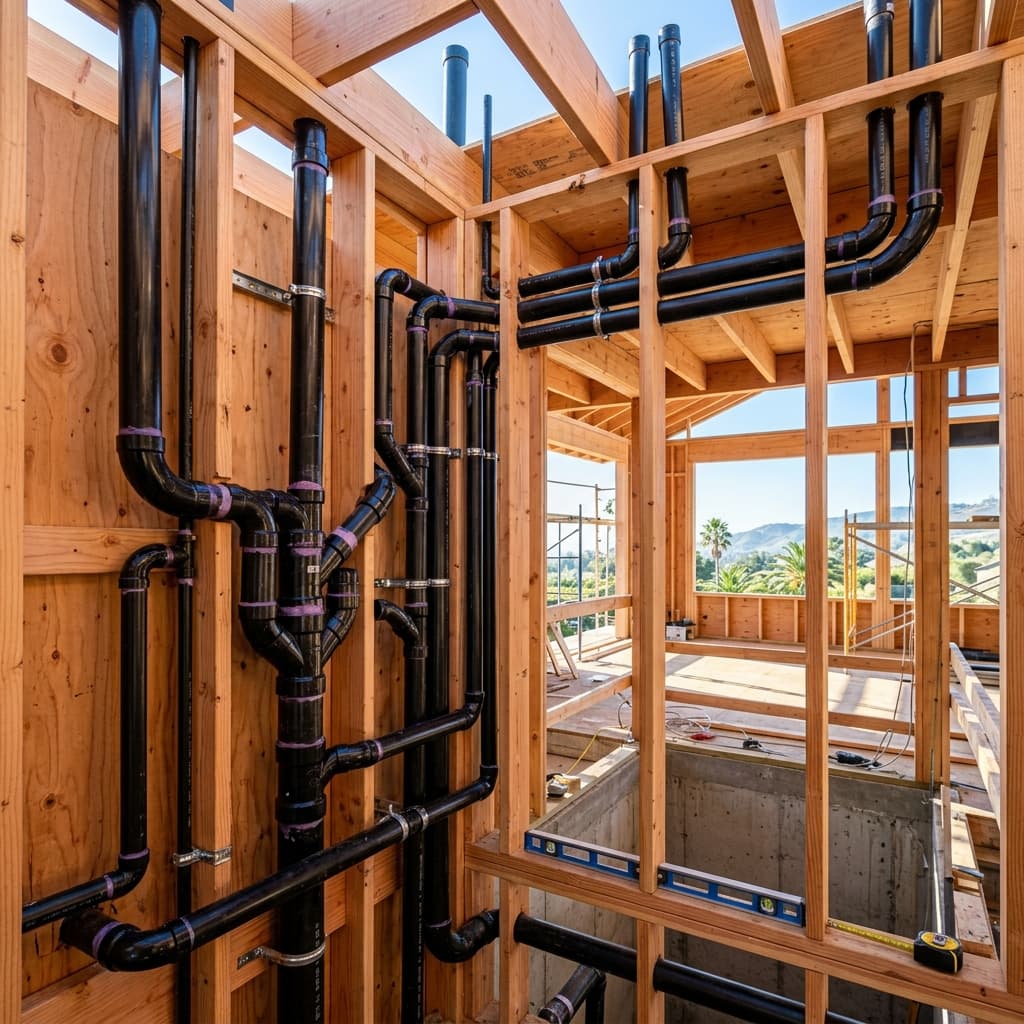
A combination drain, waste, and vent system integrates three critical functions into a single, coordinated network:
Drainage Component: Collects and conveys wastewater from fixtures to the building sewer or septic system. Waste Component: Specifically handles the conveyance of solid waste and gray water from fixtures like sinks, showers, and lavatories. Vent Component: Maintains atmospheric pressure within drainage pipes, allows sewer gases to escape safely, and provides air for proper drainage performance.Unlike traditional separate systems, combination DWV design creates interdependencies where each component affects the others. A poorly sized vent can compromise drainage efficiency, while inadequate drainage slope affects vent performance.
CPC Section 403: Foundational Requirements
Section 403.1 - General Requirements
California Plumbing Code Section 403.1 establishes that all buildings must be equipped with properly designed, installed, and maintained drainage systems. The code specifically requires:
- Complete enclosure of all wastewater in tight, durable pipes
- Protection of public health and safety through proper waste conveyance
- Prevention of backflow, vapor escape, and environmental contamination
- Maintenance of trap seal integrity throughout system operation
Section 403.2 - Design and Installation Standards
CPC Section 403.2 requires all drainage system design to follow specifications within the code. This section mandates:
- Compliance with approved materials standards
- Proper sizing based on fixture units and drainage demands
- Installation in accordance with manufacturer specifications
- Testing and inspection requirements before system operation
Drain, Waste, and Vent System Components
Drainage Pipes: The Foundation
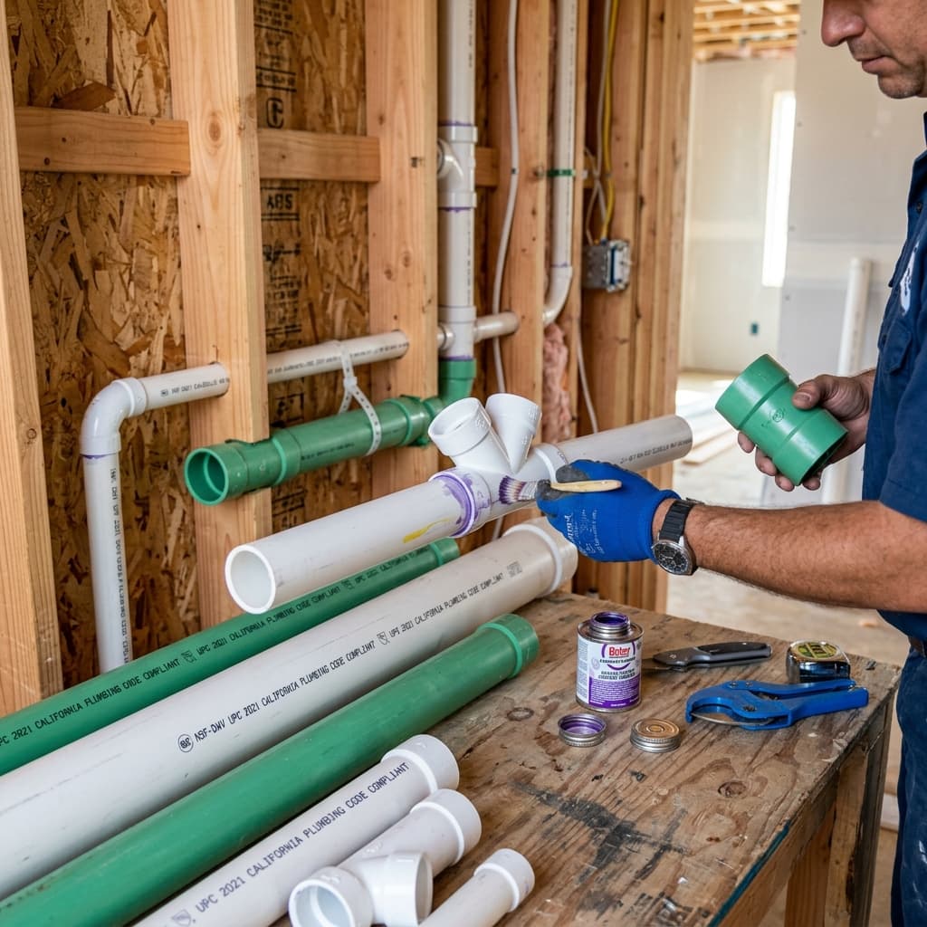
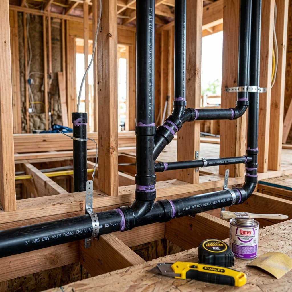
Drainage pipes form the backbone of your DWV system. CPC Section 405 specifies acceptable materials including:
- Cast iron pipe (CIP)
- PVC (polyvinyl chloride)
- ABS (acrylonitrile butadiene styrene)
- Copper
- Galvanized steel (limited applications)
Waste Pipes: Specialized Conveyance
Waste pipes specifically handle fecal matter and gray water. These require:
- Minimum 1/4-inch-per-foot slope (per CPC Section 422.2)
- Sizing based on fixture units according to CPC Table 422.1
- Direct connection to the building drain or building sewer
- Cleanout access at regular intervals (per CPC Section 408.3)
Vent Pipes: Pressure Maintenance
Vent pipes maintain proper pressure within the drainage system. Their primary functions include:
- Releasing sewer gases safely above the roofline
- Admitting outside air to facilitate drainage
- Preventing trap seal loss from siphonage
- Allowing equalization of pressure during peak drainage events
Understanding Fixture Units and Drainage Demand
Fixture Unit Assignments (CPC Table 422.1)
The California Plumbing Code assigns fixture unit values to each plumbing fixture based on its drainage demand:
| Fixture Type | Fixture Units | |---|---| | Water closet (WC) | 4 | | Lavatory | 1 | | Bathtub | 2 | | Shower | 2 | | Kitchen sink | 2 | | Washing machine | 2 | | Floor drain | 1 |
These values represent standardized flow rates based on typical usage patterns. When designing a combination DWV system, you must:
- Identify all fixtures served by the drainage system
- Assign fixture units according to CPC Table 422.1
- Sum total fixture units for each drainage branch
- Select pipe sizes based on total fixture units and drainage slope
Drainage Pipe Sizing: The Calculation Method
Step-by-Step Sizing Process
CPC Section 403 requires drainage pipes be sized to handle the maximum simultaneous discharge without backup or overflow. The sizing process follows this methodology:
Step 1: Determine Fixture Unit Load Calculate total fixture units for all fixtures draining into each pipe segment. Step 2: Establish Slope Confirm minimum 1/4-inch-per-foot slope for drainage pipes (or 1/8-inch-per-foot for certain commercial applications per CPC Section 422.2). Step 3: Reference CPC Table 422.1 Match fixture units and slope to appropriate pipe diameter. Step 4: Verify Cleanout Access Ensure cleanout placement complies with CPC Section 408.3.Example Calculation
Scenario: A residential bathroom with:- 1 water closet (4 fixture units)
- 1 lavatory (1 fixture unit)
- 1 bathtub (2 fixture units)
- Total: 7 fixture units
- 7 fixture units requires a minimum 3-inch drainage pipe
Vent Sizing Calculations: Critical Design Elements
Understanding Vent Stack Requirements
CPC Section 403 establishes that vent pipes must be sized based on:
- Developed length (actual pipe length accounting for fittings)
- Number of fixture units connected to the vent
- Slope and configuration of connected drainage pipes
CPC Table 424.2: Vent Stack Sizing
California Plumbing Code Table 424.2 provides vent stack sizing based on:
| Fixture Units | 1/4" Slope | 1/8" Slope | |---|---|---| | 1-7 | 1.5" | 1.5" | | 8-16 | 2" | 2" | | 17-24 | 2.5" | 2.5" | | 25-50 | 3" | 3" |
Critical Concept: The developed length of the vent stack directly affects sizing. A 40-foot vent serving 15 fixture units may require a larger diameter than a 15-foot vent serving the same load.Wet Venting vs. Combination Venting
In combination DWV systems, you'll encounter two primary venting strategies:
Wet Venting: A single pipe serves as both waste conveyance and vent. Only specific conditions allow wet venting per CPC Section 426. Typical wet vent requirements:- Maximum 2 inches diameter
- Fixtures must be on the same level
- Specific fixture combinations allowed (typically lavatory to water closet)
- Greater flexibility in fixture arrangements
- Better protection against pressure imbalances
- More reliable trap seal maintenance
Trap Seal Protection: The Core of DWV Design
Why Trap Seals Matter
Every plumbing fixture drain must have a trap seal—a water barrier that prevents sewer gases from entering the building. CPC Section 403 requires maintaining trap seals under all operating conditions.
Trap seals fail through:
- Siphonage: Improper venting creates negative pressure, pulling water from the trap
- Blow-out: Positive pressure forces water from the trap
- Evaporation: Water seal gradually evaporates in unused fixtures
- Back-venting: Improper vent configuration allows reverse flow
Preventing Trap Seal Loss
Proper combination DWV design prevents these failures through:
- Adequate vent sizing to maintain atmospheric pressure
- Proper slope (1/4-inch-per-foot) to prevent standing water
- Appropriate fixture spacing to prevent siphonage
- Vent termination above the roofline or through proper air admittance devices
Common DWV System Design Errors
Understanding what NOT to do is as important as understanding proper design. Frequent code violations include:
Undersized Vents
Installing 1.5-inch vents where 2-inch vents are required causes pressure imbalances and trap seal loss.Improper Slope
Drainage pipes with less than 1/4-inch-per-foot slope trap solids and create blockage potential.Excessive Horizontal Vent Runs
Long horizontal vents without adequate slope or sizing create back-venting conditions.Improper Fixture Connections
Connecting incompatible fixtures to wet vent systems (for example, connecting a kitchen sink to a water closet wet vent violates CPC Section 426.2).Inadequate Cleanout Access
Failing to provide cleanouts at required intervals prevents proper system maintenance and creates code violations per CPC Section 408.3.CPC Section 403 Compliance Checklist
When designing or inspecting combination DWV systems, verify:
- [ ] All drainage pipes sized per CPC Table 422.1 based on fixture units
- [ ] Minimum 1/4-inch-per-foot slope maintained throughout system
- [ ] All vents sized per CPC Table 424.2 based on developed length and fixture units
- [ ] Trap seals present on all fixtures with appropriate protection
- [ ] Cleanout access provided per CPC Section 408.3 requirements
- [ ] All materials approved per CPC Section 405
- [ ] Proper separation maintained between potable water and drainage lines
- [ ] System tested and inspected before occupancy
- [ ] Vent termination complies with roofing and construction requirements
- [ ] Backwater valves installed where required per flood zone requirements
Practical Applications for Licensed Professionals
Residential Multi-Story Design
Multi-story residential buildings require:
- Separate drainage stacks for each story (typically)
- Vent stacks sized for cumulative fixture loads
- Proper grading and slope throughout
- Accessible cleanouts at grade and intermediate levels
Commercial Building Integration
Commercial DWV systems often include:
- Larger diameter pipes handling significant simultaneous loads
- More complex pressure dynamics from high-volume usage
- Possible use of pressure systems or alternative materials
- Integration with storm drainage and special waste systems
Inspection and Troubleshooting
Licensed professionals must recognize symptoms of DWV design failures:
- Slow drainage indicating inadequate slope or sizing
- Gurgling sounds suggesting negative pressure conditions
- Fixture backup indicating blockages or insufficient capacity
- Sewer odors indicating trap seal loss or vent issues
Exam Preparation Strategies
Key CPC Sections to Master
- CPC Section 403: General drainage system requirements
- CPC Section 404: Materials and connections
- CPC Section 405: Pipe materials and standards
- CPC Section 408: Cleanouts and access
- CPC Section 422: Trap, fixture, and drainage sizing
- CPC Section 424: Vent sizing and configuration
- CPC Section 426: Wet venting requirements
Practice Calculation Problems
Work through these types of problems:
- Fixture unit summation: Given multiple fixtures, calculate total units requiring drainage
- Pipe sizing: Match fixture units to required pipe diameter
- Vent sizing: Determine vent diameter based on developed length and fixture load
- Slope verification: Confirm proper slope and identify violations
- Code compliance: Identify which scenarios violate specific CPC sections
Study Tips for C-36 Success
- Create flash cards for fixture unit values (Table 422.1)
- Develop mental models of how negative/positive pressure affects trap seals
- Practice reading and interpreting sizing tables
- Work through complete system designs, not just individual components
- Study real-world failure scenarios to understand consequences of design errors
Conclusion: Mastery of DWV System Design
Understanding combination drain, waste, and vent system design under CPC Section 403 represents a cornerstone of plumbing professional competency. The California Plumbing Code drainage system requirements reflect decades of engineering knowledge and real-world problem-solving.
Success on the C-36 Part 2 examination requires:
- Thorough knowledge of CPC Section 403 and related sections
- Proficiency with fixture unit calculations and sizing tables
- Understanding of pressure dynamics and trap seal protection
- Recognition of common design errors and code violations
- Application ability to solve real-world design scenarios